A1.2 Logic Gates & Boolean Logic
THEME A: SYSTEM FUNDAMENTALS
Logic Gates & Boolean Logic
Logic gates are the building blocks of digital circuits. In this section, we cover standard logic gates, their symbols, truth tables, and Boolean algebra.
Standard Logic Gates Comparison
| Gate Name | Symbols | Shapes |
|---|---|---|
| OR | +, ∨, || | 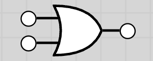 |
| AND | *, ∧, & | 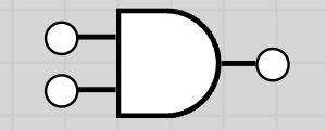 |
| NOT | ~, ¬, ! | 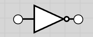 |
| XOR | ⊕, ∨̅ | 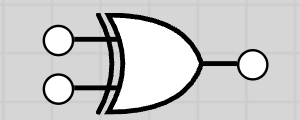 |
| XNOR | ⊙, ≡, XNOR | 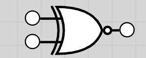 |
| NAND | ∧̅, ↑ | 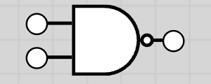 |
| NOR | ∨̅, ↓ | 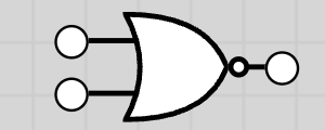 |
Logic Gate Symbols & Truth Tables
Logic gates are electronic circuits that process binary inputs (0/1) to produce a binary output.
- • Six logic gates in syllabus: NOT, AND, OR, NAND, NOR, XOR
- • Truth table: lists all possible input combinations and the resulting output
- • For n inputs → possible rows = 2n (e.g., 3 inputs → 8 rows)
Binary Values: 1 → True, 0 → False
NOT Gate
The NOT gate inverts the input. Output is 1 if input is 0, and output is 0 if input is 1.
Truth Table
| A | NOT A |
|---|---|
| 0 | 1 |
| 1 | 0 |
AND Gate
The AND gate output is 1 only if both inputs are 1.
Truth Table
| A | B | A AND B |
|---|---|---|
| 0 | 0 | 0 |
| 0 | 1 | 0 |
| 1 | 0 | 0 |
| 1 | 1 | 1 |
OR Gate
The OR gate output is 1 if at least one input is 1.
Truth Table
| A | B | A OR B |
|---|---|---|
| 0 | 0 | 0 |
| 0 | 1 | 1 |
| 1 | 0 | 1 |
| 1 | 1 | 1 |
NAND Gate (NOT AND)
The NAND gate output is 1 except when both inputs are 1. It is the inverse of AND.
Truth Table
| A | B | A NAND B |
|---|---|---|
| 0 | 0 | 1 |
| 0 | 1 | 1 |
| 1 | 0 | 1 |
| 1 | 1 | 0 |
NOR Gate (NOT OR)
The NOR gate output is 1 only if both inputs are 0. It is the inverse of OR.
Truth Table
| A | B | A NOR B |
|---|---|---|
| 0 | 0 | 1 |
| 0 | 1 | 0 |
| 1 | 0 | 0 |
| 1 | 1 | 0 |
XOR Gate (Exclusive OR)
The XOR gate output is 1 if inputs are different. Output is 0 if inputs are the same.
Truth Table
| A | B | A XOR B |
|---|---|---|
| 0 | 0 | 0 |
| 0 | 1 | 1 |
| 1 | 0 | 1 |
| 1 | 1 | 0 |
XNOR Gate (Exclusive NOR)
The XNOR gate is the inverse of XOR. The output is 1 if the inputs are the same (both 0 or both 1).
Truth Table
| A | B | A XNOR B |
|---|---|---|
| 0 | 0 | 1 |
| 0 | 1 | 0 |
| 1 | 0 | 0 |
| 1 | 1 | 1 |
Logic Circuits, Expressions & Truth Tables
A logic circuit is a combination of gates to perform a task. There are three ways to represent logic:
1. Logic Circuit Diagram
Visual representation using gate symbols
2. Truth Table
Lists all inputs and corresponding output
3. Boolean Expression
Mathematical representation using operators
Conversion is possible between circuit ↔ truth table ↔ expression. Used in real systems: alarms, safety devices, sensors.
Boolean Algebra Exploration
Boolean algebra is the mathematical representation of logic using operators:
Operator Symbols
- • · or AND = AND operation
- • + or OR = OR operation
- • ̅ or NOT = NOT operation (inversion)
Operator Precedence
When evaluating Boolean expressions, operators are processed in the following order:
Precedence Order (Highest to Lowest):
- 1. Brackets ( )
- 2. NOT
- 3. AND
- 4. OR
Example: For the expression A AND B OR NOT C, the evaluation order is: NOT C first, then A AND B, then OR.
Key Terms
Logic Gate
Electronic device performing a logical operation (NOT, AND, OR, NAND, NOR, XOR)
Logic Circuit
Group of logic gates working together for a function
Truth Table
Lists all inputs and corresponding output
Boolean Algebra
Mathematical representation of logic (· = AND, + = OR, ̅ = NOT)
Combinational Logic: Adders & Subtractors
Half Adder
A Half Adder is a digital circuit that adds two single binary digits (A and B). It produces two outputs: Sum (S) and Carry (C).
Truth Table
| A | B | Sum (S) | Carry (C) |
|---|---|---|---|
| 0 | 0 | 0 | 0 |
| 0 | 1 | 1 | 0 |
| 1 | 0 | 1 | 0 |
| 1 | 1 | 0 | 1 |
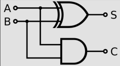
Half Adder Circuit Diagram
Boolean Expressions:
Sum = A XOR B
Carry = A AND B
Karnaugh Maps for Half Adder
K-Map for Sum (S)
| A \ B | 0 | 1 |
|---|---|---|
| 0 | 0 | 1 |
| 1 | 1 | 0 |
Sum = A ⊕ B (XOR pattern)
K-Map for Carry (C)
| A \ B | 0 | 1 |
|---|---|---|
| 0 | 0 | 0 |
| 1 | 0 | 1 |
Carry = A · B (AND pattern)
Half Subtractor
A Half Subtractor is a combinational circuit that subtracts one bit from another. It produces two outputs: Difference (D) and Borrow (B).
Truth Table
| A | B | Diff (D) | Borrow (B) |
|---|---|---|---|
| 0 | 0 | 0 | 0 |
| 0 | 1 | 1 | 1 |
| 1 | 0 | 1 | 0 |
| 1 | 1 | 0 | 0 |
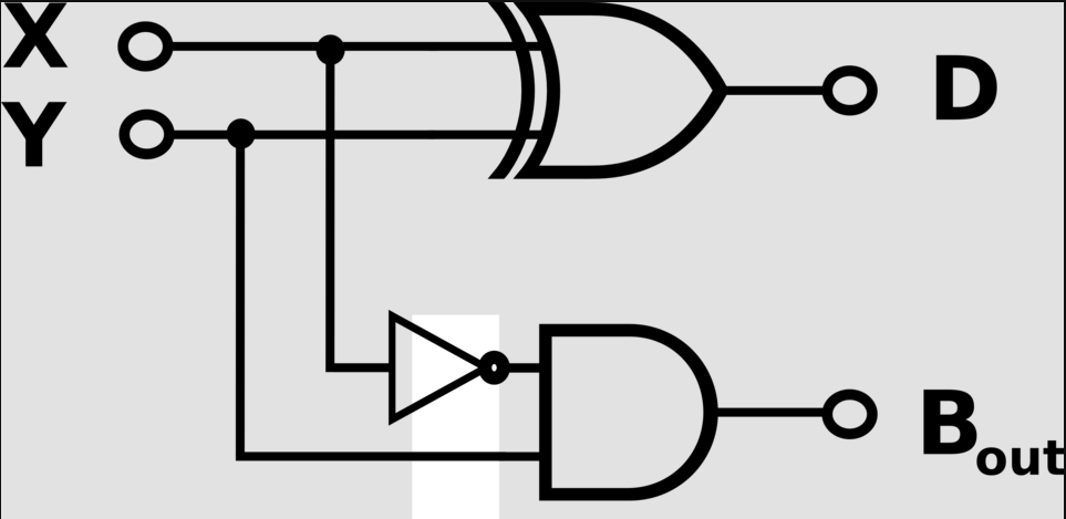
Half Subtractor Circuit Diagram
Boolean Expressions:
Diff = A XOR B
Borrow = (NOT A) AND B
Karnaugh Maps for Half Subtractor
K-Map for Difference (D)
| A \ B | 0 | 1 |
|---|---|---|
| 0 | 0 | 1 |
| 1 | 1 | 0 |
Diff = A ⊕ B (XOR pattern)
K-Map for Borrow (B)
| A \ B | 0 | 1 |
|---|---|---|
| 0 | 0 | 1 |
| 1 | 0 | 0 |
Borrow = A̅ · B (NOT A AND B)
Karnaugh Maps (K-Maps)
Karnaugh Maps (K-Maps) provide a systematic method to simplify Boolean expressions. Instead of using algebraic laws, we map the truth table values onto a grid and group 1s to find the simplest expression.
Key Advantages:
- Visual method makes it easier to spot simplifications.
- Minimizes the number of logic gates needed (reducing cost and complexity).
- Automatic elimination of redundant variables.
Structure of a 2-Variable K-Map
For 2 variables (A, B), we have 22 = 4 cells. The input combinations are arranged so that only one bit changes between adjacent cells (Gray Code order).
| A \ B | 0 | 1 |
|---|---|---|
| 0 | Cell 00 | Cell 01 |
| 1 | Cell 10 | Cell 11 |
Grouping Rules: Group adjacent 1s in powers of 2 (1, 2, 4, 8...). Groups can wrap around the edges. Larger groups = simpler terms.
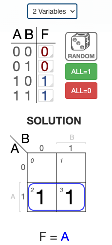
2-Variable K-Map Examples
Example 1
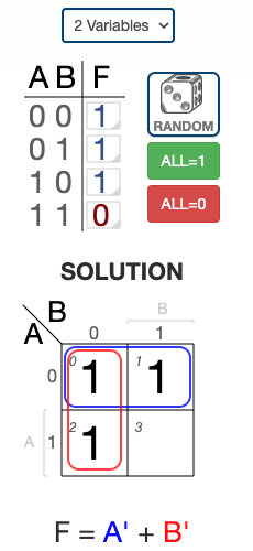
Example 2
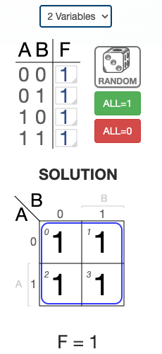
Example 3
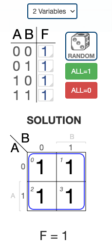
Example 4
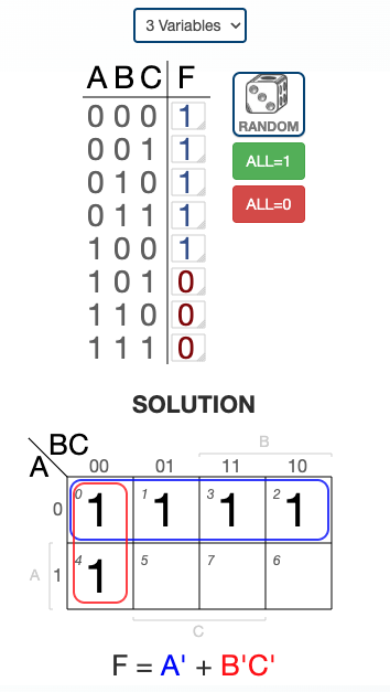
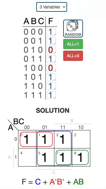
3-Variable K-Map Examples
Example 1
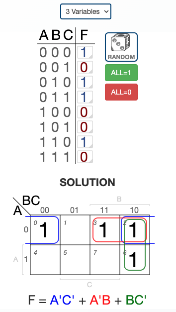
Example 2
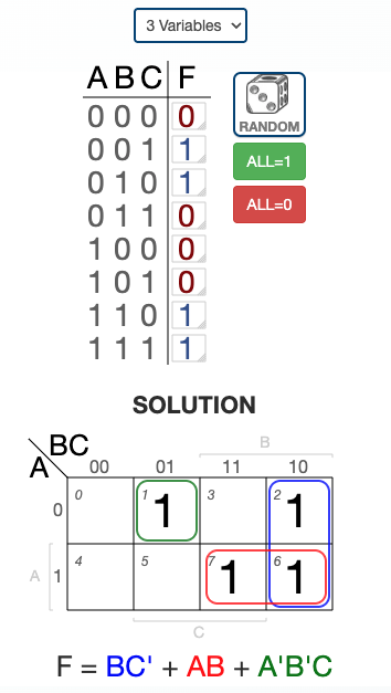
Example 3
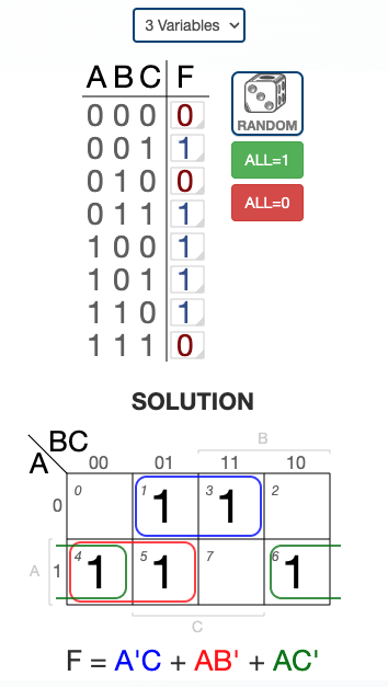
Example 4
Example 5
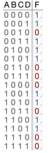
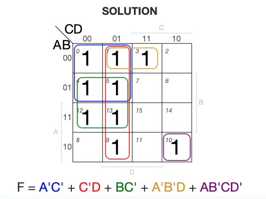
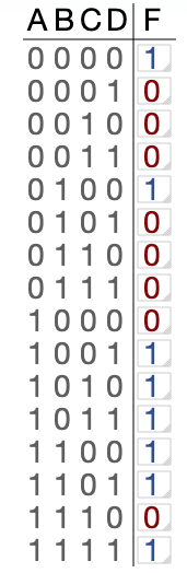
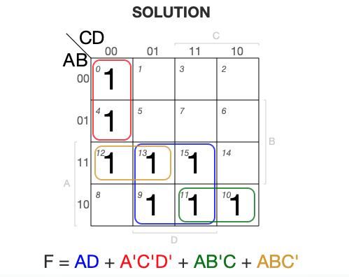
4-Variable K-Map Examples
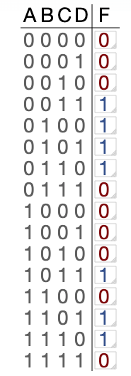
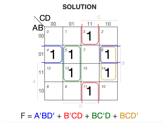
1Example 1
Truth Table
K-Map Simplification
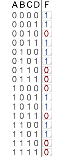
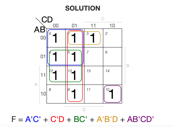
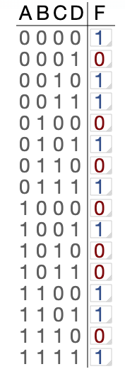
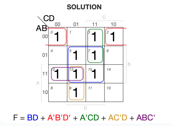
2Example 2
Truth Table
K-Map Simplification
3Example 3
Truth Table
K-Map Simplification
4Example 4
Truth Table
K-Map Simplification
5Example 5
Truth Table
K-Map Simplification
Worked Examples
Example 1: A AND B OR NOT C
Expression: A AND B OR NOT C
Evaluation order: NOT C first, then A AND B, then OR
Truth Table
| A | B | C | NOT C | A AND B | Result |
|---|---|---|---|---|---|
| 0 | 0 | 0 | 1 | 0 | 1 |
| 0 | 0 | 1 | 0 | 0 | 0 |
| 0 | 1 | 0 | 1 | 0 | 1 |
| 0 | 1 | 1 | 0 | 0 | 0 |
| 1 | 0 | 0 | 1 | 0 | 1 |
| 1 | 0 | 1 | 0 | 0 | 0 |
| 1 | 1 | 0 | 1 | 1 | 1 |
| 1 | 1 | 1 | 0 | 1 | 1 |
Example 2: X = (A AND NOT B) OR (NOT A AND B)
This expression is equivalent to XOR operation.
Truth Table
| A | B | NOT B | A & !B | NOT A | !A & B | X |
|---|---|---|---|---|---|---|
| 0 | 0 | 1 | 0 | 1 | 0 | 0 |
| 0 | 1 | 0 | 0 | 1 | 1 | 1 |
| 1 | 0 | 1 | 1 | 0 | 0 | 1 |
| 1 | 1 | 0 | 0 | 0 | 0 | 0 |
Example 3: Y = (A OR B) AND (NOT (A AND B))
Truth Table
| A | B | A AND B | NOT (A & B) | A OR B | Y |
|---|---|---|---|---|---|
| 0 | 0 | 0 | 1 | 0 | 0 |
| 0 | 1 | 0 | 1 | 1 | 1 |
| 1 | 0 | 0 | 1 | 1 | 1 |
| 1 | 1 | 1 | 0 | 1 | 0 |
Example 4: Complex Logic Circuit
For complex circuits with intermediate outputs, work step by step through each gate.
Tip: When analyzing complex circuits, identify intermediate outputs (like P, Q) and build the truth table column by column, working from inputs to final output.
Examination Tip
Make sure you can recognize both the standard circuit symbols and the block shapes. In exams, you may be asked to draw these symbols clearly.