3.3 Data Storage
Primary Memory
What is Primary Memory?
Internal Memory Directly Accessible by CPU (Eg. RAM, ROM, Cache)
RAM (Random Access Memory)
What does RAM do?
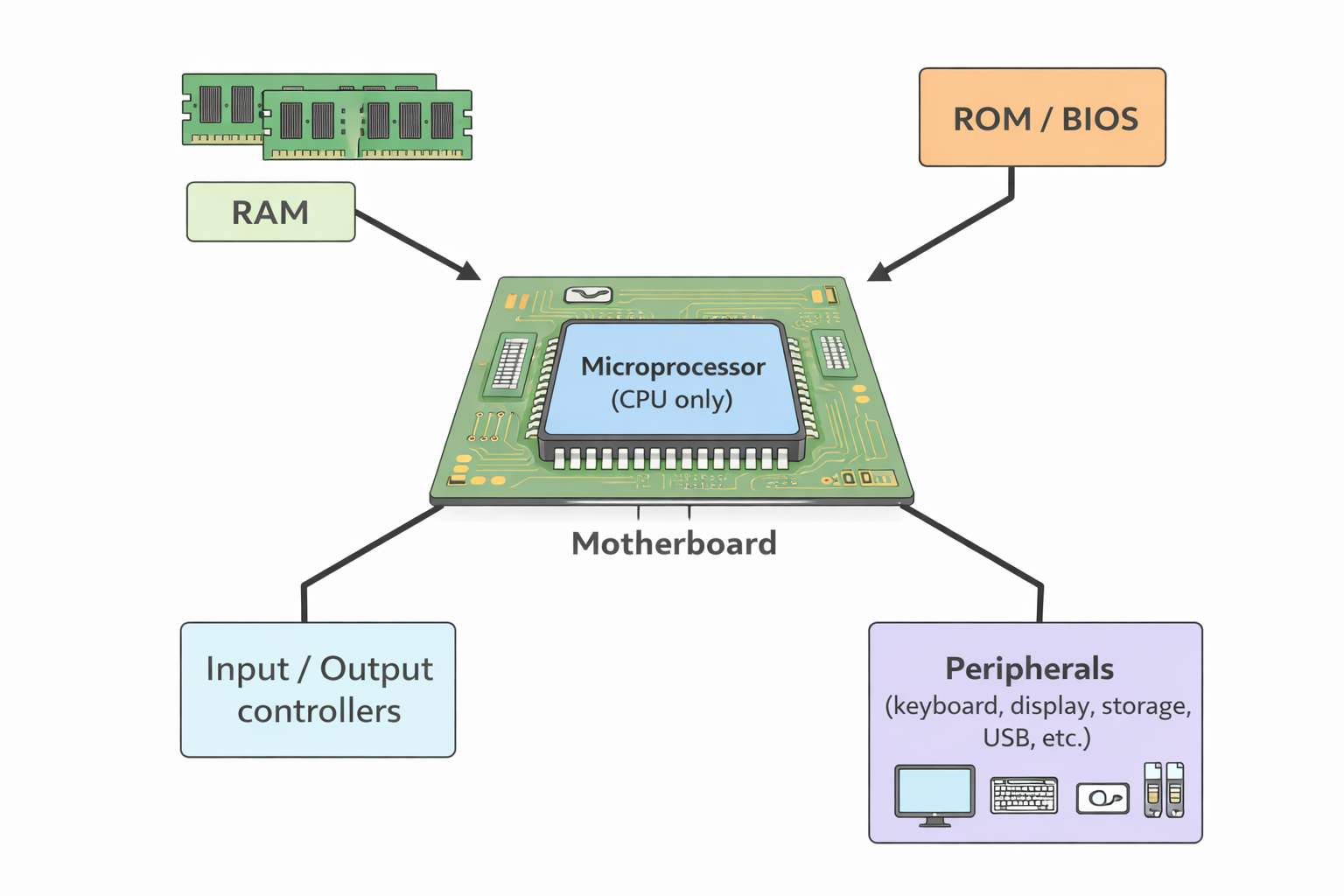
RAM is the computer's temporary workspace where data and programs are stored while the computer is running. Think of it as the computer's "desk" where it keeps everything it's currently working on.
- • Stores active programs: When you open an application (like a web browser or word processor), it loads into RAM so the CPU can access it quickly.
- • Holds data being processed: The CPU reads and writes data to RAM during calculations and operations.
- • Enables multitasking: Multiple programs can run simultaneously because each has space in RAM.
- • Volatile storage: Data in RAM is lost when the computer is turned off (unlike hard drives which keep data permanently).
- • Fast access: RAM is much faster than secondary storage (like hard drives), allowing the CPU to quickly retrieve needed data.
Volatile memory that stores data temporarily while a computer is running. It allows quick access to data, improving system performance. RAM can be increased to boost speed.
DRAM (Dynamic RAM)
- • Needs constant refreshing
- • Built using Capacitors/Transistors
- • Less expensive
- • Higher capacity
SRAM (Static RAM)
- • Faster
- • Doesn't require refreshing
- • Built using Flip Flops
- • Used in CPU caches
- • More expensive
- • Lower capacity
DRAM vs SRAM - Detailed Comparison
| Aspect | DRAM (Dynamic RAM) | SRAM (Static RAM) |
|---|---|---|
| How it works | Uses capacitors to store charge (1 or 0). Capacitors leak charge over time, so data must be refreshed thousands of times per second. | Uses flip-flops (transistor circuits) that maintain their state as long as power is supplied. No refreshing needed. |
| Speed | Slower (access time: ~50-100 nanoseconds) | Faster (access time: ~1-10 nanoseconds) |
| Cost | Less expensive per bit | More expensive per bit |
| Capacity | Higher capacity (can store more data in same space) | Lower capacity (takes more space for same amount of data) |
| Power consumption | Lower power consumption | Higher power consumption |
| Where it's used | Main system memory (RAM modules in computers, smartphones) | CPU cache memory, registers, and other high-speed applications |
| Density | Higher density (more bits per chip) | Lower density (fewer bits per chip) |
Why use DRAM for main memory? Even though SRAM is faster, DRAM is used for main system RAM because it's much cheaper and can store more data in the same physical space. The speed difference is acceptable for main memory, while SRAM's speed is critical for CPU cache.
ROM (Read-Only Memory)
What does ROM do?
ROM stores permanent, essential instructions that the computer needs to start up and operate. Unlike RAM, ROM retains its data even when the computer is turned off (non-volatile).
- • Stores BIOS (Basic Input/Output System): Contains the fundamental instructions needed to initialize hardware components when the computer starts.
- • Boot process: When you turn on your computer, ROM provides the first instructions that tell the CPU how to load the operating system from the hard drive.
- • Hardware configuration: Stores settings and firmware that control how hardware components communicate with each other.
- • Permanent storage: Data in ROM is "burned in" during manufacturing and typically cannot be changed by users (though modern systems use EEPROM/Flash which can be updated).
- • Critical system functions: Contains low-level routines that are essential for the computer to function, even before the operating system loads.
- •Non-volatile memory that stores permanent data needed by the computer
- •Stores permanent data such as the BIOS, Boot Routines
- •It cannot be modified or written to by the user
Types of ROM
PROM (Programmable ROM)
Can be programmed once by the user using special equipment, but cannot be erased or reprogrammed.
EPROM (Erasable Programmable ROM)
Can be erased using ultraviolet light and then reprogrammed. Requires removal from the computer for erasing.
EEPROM (Electrically Erasable Programmable ROM)
Can be erased and reprogrammed electrically while still in the computer. Used in modern BIOS/UEFI systems.
Flash Memory
A type of EEPROM that can be erased in blocks. Used in USB drives, SSDs, and modern BIOS chips.
RAM vs ROM - Complete Comparison
| Aspect | RAM (Random Access Memory) | ROM (Read-Only Memory) |
|---|---|---|
| Full Form | Random Access Memory | Read-Only Memory |
| Volatility | Volatile - Data is lost when power is turned off | Non-volatile - Data is retained even when power is turned off |
| Read/Write | Read and Write - Data can be both read from and written to | Read-Only - Data can only be read (cannot be modified by user) |
| Speed | Fast access speed (nanoseconds) | Slower than RAM |
| Capacity | Large capacity (GBs - typically 4GB to 32GB+ in modern computers) | Smaller capacity (MBs - typically a few MBs) |
| Cost | More expensive per unit of storage | Less expensive per unit of storage |
| What it stores | • Currently running programs • Active data being processed • Operating system (while running) • Application data | • BIOS (Basic Input/Output System) • Boot routines • Firmware • System startup instructions |
| When it's used | During normal computer operation - constantly accessed by CPU | During startup/boot process and for system configuration |
Key Takeaway: RAM is like your computer's "workspace" - it holds everything you're currently working on, but it's cleared when you turn off the computer. ROM is like the computer's "instruction manual" - it contains the essential instructions needed to start up and operate, and these instructions remain even when the power is off.
Secondary and Off-line Storage
- •NON Volatile!
- •High capacity
- •Slower Memory
- •CPU does not have direct access
Registers vs Cache vs RAM Comparison
| Aspect | Registers | Cache Memory | RAM |
|---|---|---|---|
| Location | Inside the CPU | Close to the CPU, either on-chip or nearby | On the motherboard, separate from the CPU |
| Speed | Fastest (measured in nanoseconds) | Very fast, but slower than registers | Slower than cache, but faster than secondary storage |
| Size | Smallest (a few bytes, e.g., 32-bit, 64-bit) | Larger than registers, but smaller than RAM (KB to MB) | Largest among the three (GBs) |
| Function | Temporarily holds data for immediate processing by the CPU | Stores frequently accessed data and instructions to speed up processing | Temporarily stores data and programs needed by the CPU |
| Access Time | Almost instantaneous (nanoseconds) | Extremely fast (nanoseconds) | Fast (tens of nanoseconds) |
| Volatility | Volatile (loses data when power is off) | Volatile | Volatile |
Magnetic Storage
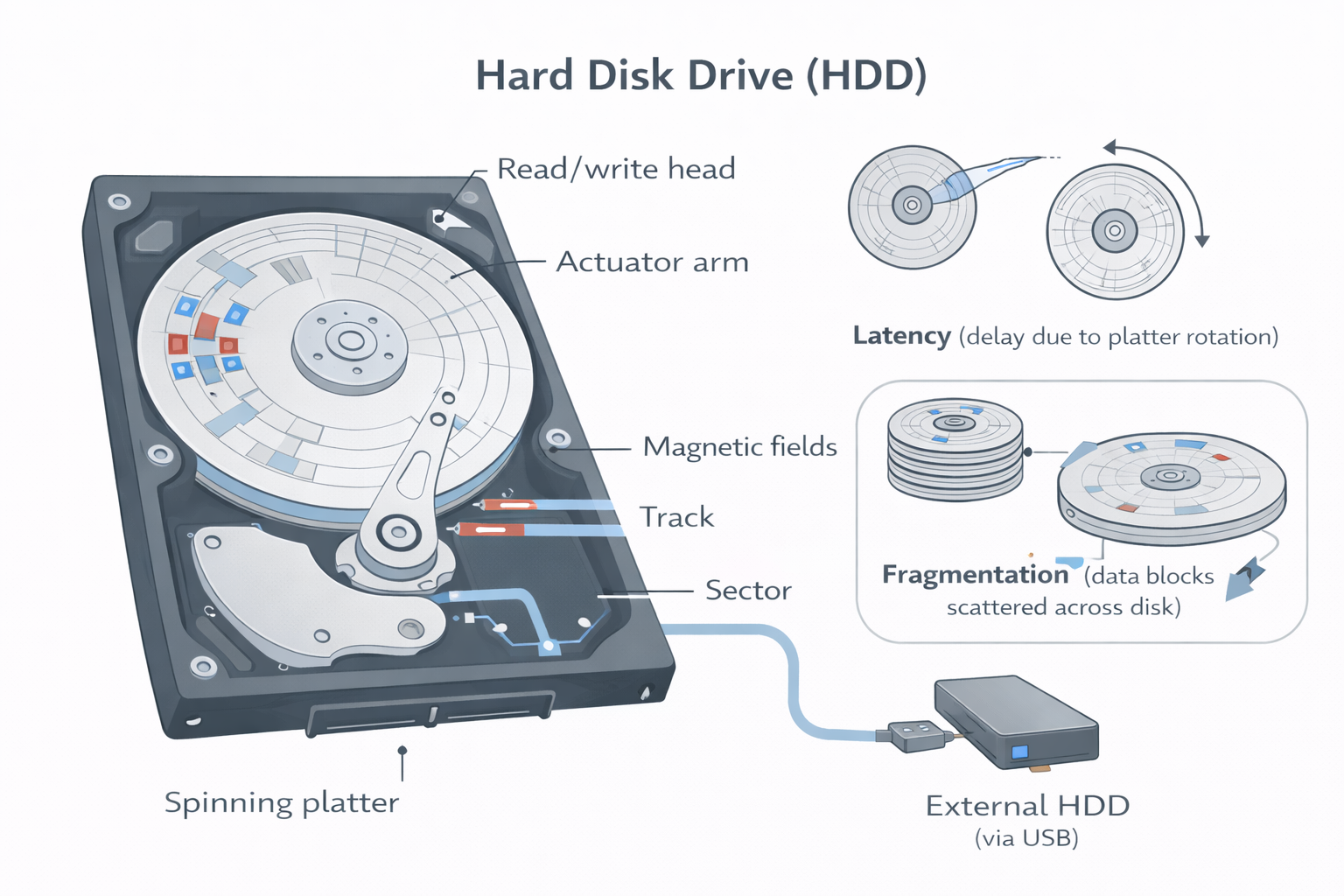
Hard Disk Drives (HDD)
- •Data stored on spinning platters using magnetic fields
- •Accessed via read/write heads
- •Data stored in sectors/tracks
- •Performance affected by latency and fragmentation
- •Can be external (USB-connected)
- •Have Large Storage Capacities
- •Slower access times due to mechanical movements
Solid State Storage
Solid State Drives (SSD)
- •No moving parts = faster, reliable, and quieter
- •Uses NAND Flash to store bits as electrical charges
- •Lower power consumption, suitable for laptops
- •Must be used yearly to retain data
- •Higher Reliability
- •Expensive
A dielectric coating separates the two transistors, which allows the floating gate transistor to retain its charge (which is why the memory is non-volatile).
The main drawback of SSD is still the longevity of the technology (although this is becoming less of an issue). Most solid state storage devices are conservatively rated at only 20GB of write operations per day over a three year period – this is known as SSD endurance.
Flash Memory / USB Sticks
- •Portable, lightweight
- •Often used with dongles for secure software use
- •Small, portable storage devices that use solid-state technology, often connected via USB ports. Commonly used for transferring files and as backup storage
How Flash Storage Works:
Past Paper- •Uses transistors/controls gates/floating gates
- •Can be NAND/NOR technology // Can use flip-flops
- •Stores data by flashing it onto the chips/device
- •Controlling/using the flow of electrons through/using transistors/chips/gates
- •The electric current reaches the control gate and flows through to the floating gate to be stored
- •When data is stored, the transistor is converted from 1 to 0 / 0 to 1
Optical Storage
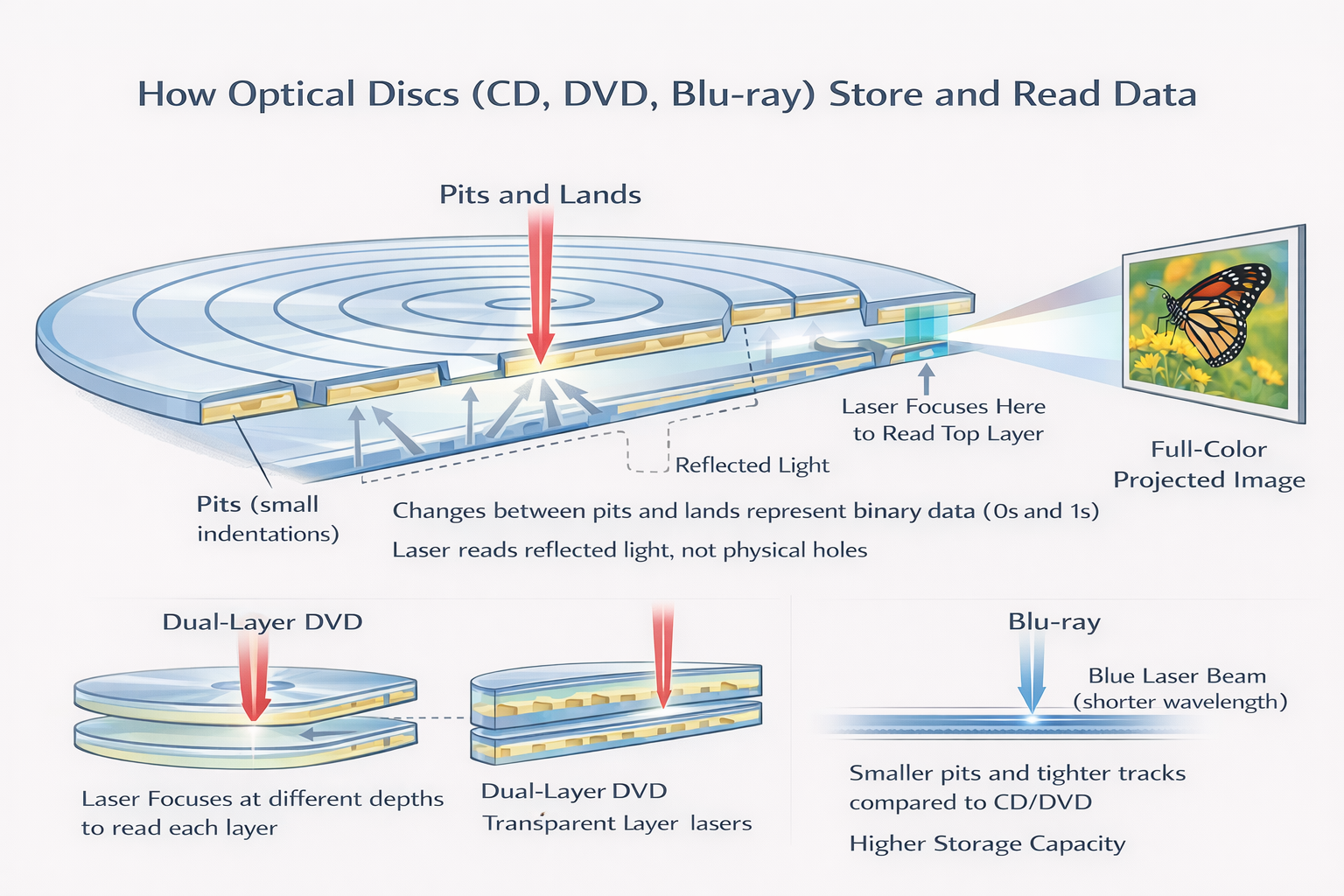
CD/DVD
- • Use lasers to read/write data
- • Data stored as pits and lands on a spiral track
- • CD/DVD-R = write once; RW = rewrite many times
DVD Dual Layer
- • Two layers read by focusing the laser differently
- • DVDs use red lasers; smaller pits = more data than CDs
Blu-ray Discs
- • Use blue lasers (405nm) → smaller pits = more capacity
- • Up to 50GB (dual-layer)
- • Allows interactivity: skipping, editing, downloading extras
Optical Storage Comparison
| Type | Laser | Capacity |
|---|---|---|
| CD | Red (780nm) | ~700MB |
| DVD | Red (650nm) | 4.7GB–8.5GB |
| Blu-ray | Blue (405nm) | 25GB–50GB |
Virtual Memory
A technique that extends RAM capacity by using part of the hard disk or SSD as additional memory. When RAM is full, data is swapped between RAM and virtual memory, allowing the system to run larger applications. This process is managed through paging, where data is divided into pages that are moved between RAM and disk storage. However, excessive use of virtual memory can lead to disk thrashing, where the system spends more time swapping data than processing it, significantly slowing down performance.
✅ Paging
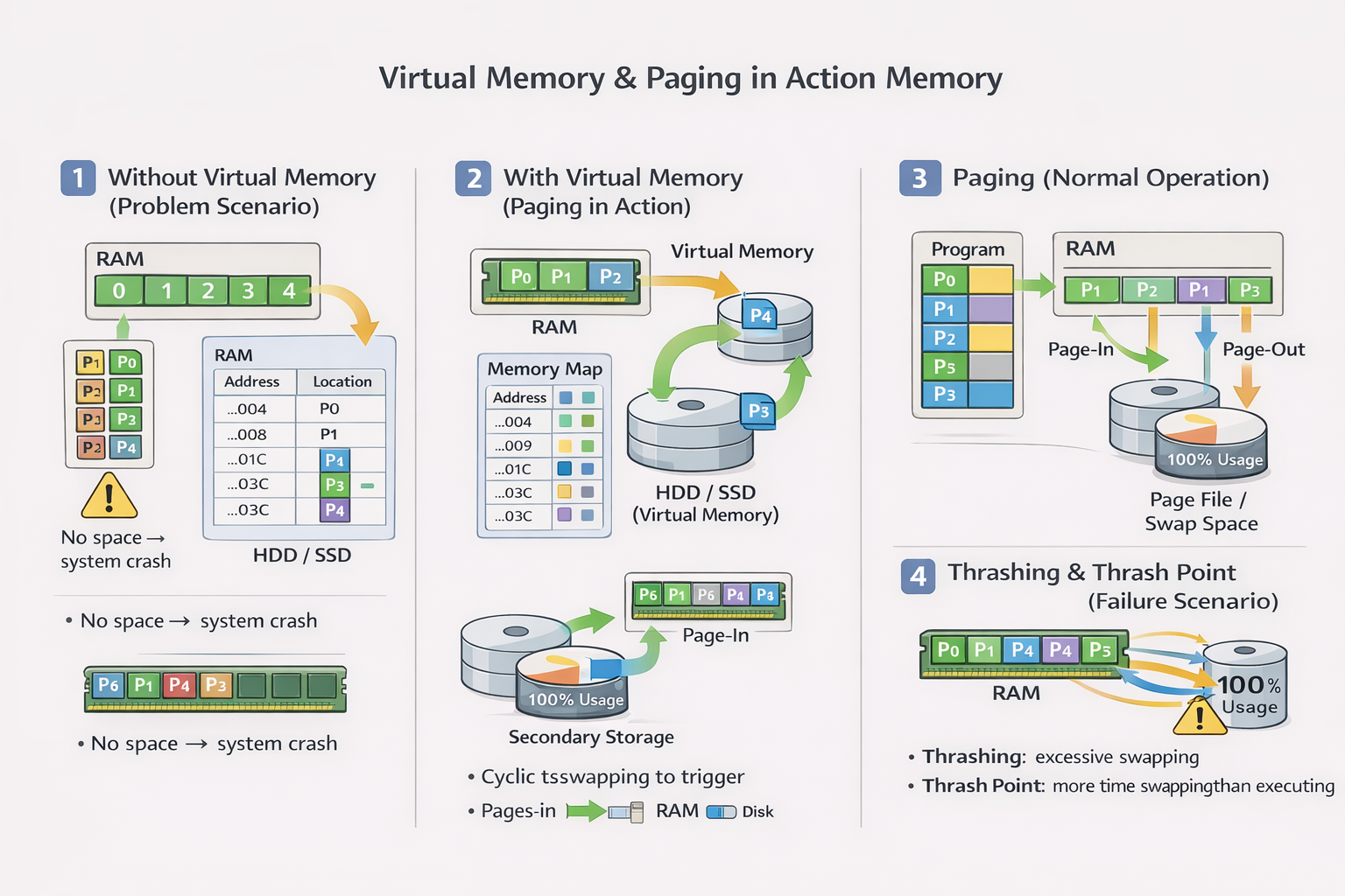
Paging is a memory management technique used in virtual memory systems.
- • The operating system divides RAM and programs into fixed-size blocks called pages
- • Each page in virtual memory corresponds to a frame in physical memory (RAM)
- • When a program runs, only the needed pages are loaded into RAM
- • If more memory is needed than what RAM can hold, some pages are moved to and from the hard disk (called the page file or swap space)
Advantage: It allows large programs to run even if there's not enough RAM, by loading only parts (pages) as needed.
❌ Page Thrashing
Page thrashing happens when the computer is spending more time swapping pages in and out of RAM than actually executing the program.
- • It usually occurs when too many programs are running or not enough RAM is available
- • The system constantly loads pages from the hard disk to RAM and removes old ones
- • This leads to a major slowdown, and performance becomes worse
Think of it like this: If you only have a small desk and you're trying to work with 10 open books, you'll keep swapping books in and out of your backpack just to find the one you need. You'll spend more time swapping books than reading — that's thrashing!
Without Virtual Memory:
Imagine 5 programs (0–4) needing access to 4 RAM blocks (0–3). Program 4 has no space → ❌ System Crash
With Virtual Memory:
- • A 32-bit memory map keeps track of where each program's data is
- • Oldest RAM block (e.g. program 0) is moved to HDD
- • New program (e.g. program 4) now uses that RAM block
- • This continues in a cycle to free up space in RAM
Benefits:
- • Run programs larger than RAM
- • Avoid system crashes
- • Cost-effective (no need to buy more RAM immediately)
Drawbacks:
- • Slower than RAM
- • Can lead to disk thrashing: excessive data swapping → slower performance → HDD wear
- • Solutions: Use SSD, increase RAM, reduce open programs
Cloud Storage
Cloud storage is a method of saving data on remote servers that are accessed over the Internet. Instead of storing files locally on your computer or USB, the data is stored in large data centres managed by companies like Google, Amazon, Microsoft, etc.
Types
- • Public: Different provider (e.g., Google Drive)
- • Private: Internal, secured by organization
- • Hybrid: Mix of both
✅ Advantages:
- • Data is available anytime, anywhere
- • Easy to share and collaborate
- • Reduces need for physical storage devices
- • Often includes automatic backup options
❌ Disadvantages:
- • Requires internet to access or update files
- • Security concerns (e.g., hacking or data breaches)
- • May involve ongoing subscription costs for large storage
🔒 Security Concerns
- • Data access by third-party
- • Disaster resilience
- • Insider misuse
- • Risk of data breaches
- • Backup failure
- • Data Leaks