2. Data Transmission
SECTION 1: THEORY FUNDAMENTALS
Data transmission refers to the transfer of data from one device to another, either within a local area network (LAN) or across vast distances over a wide area network (WAN). This chapter covers types of networks, data packets, packet switching, transmission modes, error detection methods, and encryption.
Table of Contents
2.1 Types and Methods of Data Transmission
2.2 Methods of Error Detection
2.3 Encryption

Fiber Optic Communication Infrastructure: This diagram shows how fiber optic communication cables are installed under the sea to connect different countries and continents. These cables are known as submarine fiber optic cables and form a major part of the global internet infrastructure.

Submarine Cable Installation: The diver (or underwater technician) in the image represents the human and engineering effort involved in laying, inspecting, and maintaining these cables on the ocean floor. The cable carries data as light signals, allowing information to travel over long distances at very high speeds.
2.1 Types and Methods of Data Transmission
Types of Networks

1. PAN (Personal Area Network)
- • Small-scale network for personal devices
- • Example: Bluetooth-connected devices
Advantages:
- • Secure
- • Cost-effective
Disadvantages:
- • Limited range
2. LAN (Local Area Network)
Small-scale network within a building or campus
Advantages:
- • Cost-effective resource sharing
- • Centralized data management
Disadvantages:
- • High setup costs
- • Privacy concerns
3. MAN (Metropolitan Area Network)
Covers a city or campus
Advantages:
- • High-speed communication
- • Supports large networks
Disadvantages:
- • Higher cabling costs
- • Security challenges
4. WAN (Wide Area Network)
Spans large geographical areas
Advantages:
- • Facilitates global communication
- • Supports various devices
Disadvantages:
- • High setup and maintenance costs
- • Security vulnerabilities
5. WLAN (Wireless Local Area Network)
A LAN that uses wireless communication instead of cables
- • Uses Wi-Fi technology (IEEE 802.11 standards)
- • Devices connect via wireless access points (routers)
- • Example: Home Wi-Fi networks, office wireless networks
Advantages:
- • No cables required (mobility)
- • Easy to add new devices
- • Flexible device placement
Disadvantages:
- • Security risks (requires encryption)
- • Signal interference possible
- • Limited range compared to wired LAN
What is a Node in Networking?
A node in networking refers to any device that can send, receive, or process data within a network. Nodes act as communication points that help in data transmission, storage, and routing.
2.1.1 Data Packets

- •Data when sent over long distances is broken into smaller pieces known as data packets for easier control (aka datagrams)
- •Size is 64 KiB
- •Each packet is sent separately and may take different routes to reach the destination
Packet Structure:
Header
Contains sender & receiver IP addresses, packet size, sequence number, and error-checking information
Payload
Actual data being transmitted (~64 KiB per packet)
Trailer
Includes an end marker and error-checking method (e.g., Cyclic Redundancy Check (CRC))
Why Sequence Number Exists in Data Packets
- • Correct Reassembly: Each packet in a data transmission is assigned a sequence number, allowing the receiver to arrange them in the correct order even if they arrive out of sequence
- • Error Detection and Recovery: If a packet is lost or arrives corrupted, the receiver can detect the missing sequence number and request retransmission
2.1.2 Packet Switching - Expanded Version
Packet switching is a fundamental data transmission method used in modern networking, including the Internet. It enables the efficient transfer of data by breaking messages into smaller units called packets, which are sent independently across the network. Each packet takes the most optimal route available at the time and is reassembled at the destination.
Packet Structure:

1. How Packet Switching Works
Step 1: Breaking Data into Packets
- • The original message (e.g., a photograph, email, video, or document) is broken into smaller packets of data
- • Each packet has a fixed size, typically between 512 bytes to 64 KiB
- • Each packet contains three parts:
- - Header – Contains metadata about the packet
- - Payload – Contains the actual data
- - Trailer – Contains error-checking information
Step 2: Packet Header Information
Each packet's header contains:
- • Source IP Address – Identifies the sender
- • Destination IP Address – Identifies the recipient
- • Packet Sequence Number – Used to reassemble packets in the correct order
- • Error Detection Code – Ensures data integrity (e.g., Cyclic Redundancy Check (CRC))
- • Hop Number – Helps control packet lifetime (explained later)
Step 3: Sending Packets Independently
- • Packets are sent independently, meaning they may take different routes through the network
- • Routers at each stage determine the best available path for each packet
- • The routing decision is based on:
- - Network congestion – Avoiding busy routes
- - Faulty links – Rerouting to avoid damaged paths
- - Shortest available path – Reducing latency
Step 4: Packet Routing through Network Nodes
- • The network consists of nodes (computers, routers, switches) that help forward packets toward their destination
- • Routers analyze the packet header to determine the best route
- • Each packet travels independently, possibly arriving in a different order than it was sent
Example:
- 1. Packet 1 → Router 1 → Router 4 → Router 8 → Destination
- 2. Packet 2 → Router 1 → Router 3 → Router 6 → Router 9 → Destination
- 3. Packet 3 → Router 1 → Router 5 → Router 7 → Router 10 → Destination
Step 5: Packet Reassembly at the Destination
- • Once packets arrive at the destination, they must be reassembled in the correct order
- • The packet sequence number in the header helps organize them properly
- • If any packet is missing, a request for retransmission is sent
Step 6: Error Checking and Retransmission
- • Each packet undergoes error checking (e.g., using a checksum or CRC)
- • If a packet is found to be corrupt or missing, the recipient requests a retransmission
- • This ensures that no data is lost during transmission
2. Role of Routers and Hop Numbers
Routers in Packet Switching
- • Routers are specialized devices that direct network traffic
- • Each router examines packet headers and chooses the best path dynamically
Hop Numbers to Prevent Packet Looping
- • Sometimes, a packet might keep bouncing between routers without reaching its destination
- • To prevent infinite loops, each packet is assigned a hop number
- • Every time the packet passes through a router, the hop number decreases by 1
- • If the hop number reaches zero, the packet is discarded
- • The receiving device requests a retransmission for missing packets
Example:
Router 3 (Hop: 10) → Router 5 (Hop: 9) → Router 8 (Hop: 8) → Router 11 (Hop: 7) → Router 15 (Hop: 6)
✅ Benefits of Packet Switching
- • Fast Data Transmission – Packets can be rerouted dynamically to avoid congestion
- • Fault Tolerance – If one route fails, packets take an alternative path
- • No Need for Dedicated Lines – Unlike circuit switching, no permanent connection is required
- • Scalability – Easily accommodates more users and data
- • Support for Multiple Applications – Used in emails, video streaming, VoIP, and gaming
❌ Drawbacks of Packet Switching
- • Packets Can Arrive Out of Order – Requires reordering at the destination
- • Not Ideal for Real-Time Streaming – Delays and jitter can occur in live video and audio streaming
- • Packet Loss – If packets exceed their hop limit, they get discarded
Real-World Applications of Packet Switching
Packet Switching vs. Circuit Switching
| Feature | Packet Switching | Circuit Switching |
|---|---|---|
| Data Path | Multiple, dynamic routes | Fixed, dedicated route |
| Efficiency | Highly efficient | Less efficient (dedicated path unused when idle) |
| Reliability | Packets may get lost but can be retransmitted | Reliable once connection is established |
| Flexibility | More flexible and scalable | Less flexible |
| Best Used For | Internet, emails, VoIP | Traditional telephone calls |
2.1.3 Transmission Modes
1. Simplex Transmission
Data flows in only one direction - Computer to a printer (e.g., keyboard to computer)
2. Half-Duplex Transmission
Data can travel in both directions, but only one at a time (e.g., walkie-talkies)
3. Full-Duplex Transmission
Data can flow in both directions at the same time (e.g., telephone conversations)
2.1.4 Serial and Parallel Data Transmission


Serial Transmission
- • Data is sent one bit at a time over a single channel
- • Used in USB connections
- • Slower but more reliable over long distances
Parallel Transmission
- • Multiple bits are sent simultaneously over multiple channels
- • Used in computer buses
- • Faster but may cause skewing (misalignment of bits)
Comparison: Serial vs Parallel Transmission
| Serial Transmission | Parallel Transmission |
|---|---|
| Lower risk of external interference due to fewer wires | Faster data transmission rate |
| More reliable over long distances | Works best over short distances (e.g., internal circuit boards) |
| No risk of data skew (bits stay synchronised) | Risk of skew because bits may arrive out of sync |
| Slower transmission speed | Preferred when speed is critical |
| Used for smaller amounts of data (e.g., USB) | Suitable for time-sensitive data |
| Used for long-distance communication (e.g., telephone lines) | More expensive due to extra hardware |
| Cheaper to implement due to less hardware | Easier to program input/output operations |
Practice Question
Past PaperExplain why serial transmission is more appropriate than parallel transmission in this scenario.
Answer:
- •Accurate/reliable/efficient over long distances
- •Data will arrive in order
- •Serial is cheaper to purchase/install/maintain
- •Less chance of interference / cross talk
2.1.5 Universal Serial Bus (USB)
Universal Serial Bus (USB) is a widely-used standard interface for serial data transmission between computer systems and peripheral devices (like keyboards, mice, printers, and external drives).
Key Features and Advantages:
1. Backward Compatibility
USB is designed to be backward compatible. This means that newer USB versions (like USB 3.0) can still work with older USB devices (like USB 2.0), ensuring that users don't have to replace all their peripherals when they upgrade their computers.
2. Prevention of Data Skew
Because USB uses serial transmission (sending data one bit at a time over a single wire), it completely eliminates the risk of data skew. Data skew occurs in parallel transmission when bits arrive slightly out of sync, which is a major issue over longer distances.
3. Plug-and-Play Functionality
USB supports plug-and-play device detection. When a device is plugged in, the computer's operating system automatically detects it and identifies/installs the necessary drivers, making the setup process seamless for the user.
4. Dual Transmission Modes
Depending on the device and version, USB can use both half-duplex (sending/receiving but not at the same time) and full-duplex transmission (sending and receiving simultaneously), providing flexibility for different types of data tasks.
5. Error Detection & Power Supply
USB includes built-in error detection and correction mechanisms to ensure data integrity. Additionally, it can provide power to devices (like charging a phone), eliminating the need for separate power cables for many peripherals.
2.2 Methods of Error Detection
Errors can occur during transmission due to interference, network congestion, or hardware issues. Various methods help detect and correct errors.
2.2.1 Parity Checks
A parity bit is added to each byte of data to ensure it follows an agreed parity (even or odd).
Even Parity
The number of 1s in the byte, including the parity bit, should be even. Parity is 0 for even
Odd Parity
The number of 1s should be odd. Parity is 0 for odd
How Parity Checks Work
Sender Side:
- • The sender counts the number of 1s in the data
- • It then adds a parity bit (0 or 1) based on the chosen parity scheme (even or odd)
- • The data with the parity bit is sent to the receiver
Receiver Side:
- • The receiver recounts the number of 1s in the received data (including the parity bit)
- • If the number of 1s does not match the expected parity (even or odd), an error is detected
Example of Even Parity
Let's assume we are transmitting a 7-bit binary number using even parity:
| Original Data (7 bits) | Number of 1s | Parity Bit (Even) | Transmitted Data (8 bits) |
|---|---|---|---|
| 1011001 | 4 | 0 | 01011001 |
| 1101010 | 4 | 0 | 01101010 |
| 1001101 | 4 | 0 | 01001101 |
• If the number of 1s is already even, the parity bit is 0
• If the number of 1s is odd, the parity bit is 1 to make the total even
Example of Error Detection
Now, let's say a single-bit error occurs during transmission:
| Received Data (8 bits) | Expected Even Parity | Error Detected? |
|---|---|---|
| 11011001 | 5 (Odd - Error) | ✅ Yes |
| 01101010 | 4 (Even - Correct) | ❌ No |
| 01001101 | 4 (Even - Correct) | ❌ No |
In the first case, an error is detected because the number of 1s is now odd, violating even parity. The receiver can request the sender to retransmit the data.
Limitations of Parity Checks
- • Cannot Detect All Errors: If two bits flip, the parity remains the same, and the error goes undetected
2.2.2 Checksum
A checksum value is calculated from a block of data before transmission. The receiver recalculates the checksum and compares it with the original. If they do not match, data is considered erroneous.
How Checksum Works
Sender Side:
- • The sender adds up all the binary values in the data
- • It then calculates a checksum (usually by taking the sum modulo a fixed value like 256)
- • The checksum is appended to the data before sending it
Receiver Side:
- • The receiver adds up the received data values (excluding the checksum)
- • It compares the calculated checksum with the received checksum
- • If they do not match, an error is detected
Example of Checksum Calculation
Let's say we are transmitting four 8-bit binary numbers and using an 8-bit checksum.
| Data Bytes (8-bit each) | Decimal Equivalent |
|---|---|
| 10110101 | 181 |
| 01101110 | 110 |
| 11000011 | 195 |
| 00011101 | 29 |
Step 1: Calculate Checksum
Sum all the values:
Apply modulo 256 (since we use an 8-bit checksum):
So, the checksum value is 3 (00000011 in binary).
The transmitted data is:
| Data Bytes | Checksum (8-bit) |
|---|---|
| 10110101 | 00000011 |
| 01101110 | |
| 11000011 | |
| 00011101 |
Example of Error Detection
Now, let's say a single-bit error occurs during transmission:
| Received Data Bytes | Decimal |
|---|---|
| 10110101 | 181 |
| 01101111 | 111 (error) |
| 11000011 | 195 |
| 00011101 | 29 |
| Checksum: 3 |
Recalculate: 181 + 111 + 195 + 29 = 516
516 mod 256 = 4
Since 4 ≠ 3, an error is detected, and the receiver requests retransmission.
Limitations of Checksum
- • Cannot Detect All Errors: If errors cancel each other out, the checksum might remain the same
For stronger error detection, Cyclic Redundancy Check (CRC) is often used.
2.2.3 Echo Check
The receiver sends back the received data to the sender. The sender compares it with the original. If mismatched, data is resent.
How Echo Check Works
Sender Side:
- • The sender transmits data to the receiver
- • After receiving the data, the receiver immediately sends a copy back to the sender
Receiver Side:
- • The sender compares the echoed (returned) data with the original
- • If both match, the data was transmitted correctly
- • If they do not match, an error is detected, and the sender may retransmit the data
Example of Echo Check
Suppose a sender wants to transmit the binary message: 10110101
Case 1: No Error Detected
| Original Sent Data | Received Data | Echoed Back Data | Match? | Action |
|---|---|---|---|---|
| 10110101 | 10110101 | 10110101 | ✅ Yes | Data is correct |
Case 2: Error Detected
Now, assume a bit error occurred during transmission, and the receiver gets: 10110001 instead of 10110101
| Original Sent Data | Received Data | Echoed Back Data | Match? | Action |
|---|---|---|---|---|
| 10110101 | 10110001 | 10110001 | ❌ No | Error detected, retransmit data |
Limitations of Echo Check
- • Fails for Undetected Errors: If errors occur in both directions but cancel each other out, the error may go unnoticed
- • Slower Transmission: Since data is sent twice (forward and echoed back), it increases network traffic and reduces efficiency
For better accuracy, parity checks, checksums, or CRC (Cyclic Redundancy Check) are often used instead.
Check Digits
A check digit is an error detection method used in numeric data, such as ISBNs, barcodes, and credit card numbers. It is a single digit added to the end of a number to verify its accuracy when entered or transmitted.
How Check Digits Work
- A mathematical formula is applied to the original number to calculate the check digit
- The check digit is appended to the number
- When the number is entered or scanned, the system recalculates the check digit and compares it with the transmitted one
- If they match, the number is correct. If not, an error is detected
Example of Error Detection
If a number is mistyped (e.g., 9780316066523 instead of 9780316066525), the new sum won't be a multiple of 10, flagging an error.
Common Uses of Check Digits
Example 1: ISBN 13
The check digit in ISBN 13 is the 13th digit. We will use two calculations: generating the check digit and verifying it.
Calculation 1: Generation of Check Digit
Algorithm:
- Add all the odd numbered digits together.
- Add all the even numbered digits together and multiply the result by 3.
- Add the results from step 1 and 2 together and divide by 10.
- Take the remainder. If zero, use 0. Otherwise, subtract remainder from 10 to find the check digit.
Example: 9 7 8 0 3 4 0 9 8 3 8 2
1. Odd Digits Sum: 9 + 8 + 3 + 0 + 8 + 8 = 36
2. Even Digits Sum * 3: 3 × (7 + 0 + 4 + 9 + 3 + 2) = 75
3. Total Sum: 36 + 75 = 111
4. Remainder: 111 / 10 = 11 remainder 1
5. Check Digit: 10 - 1 = 9
Final ISBN: 9 7 8 0 3 4 0 9 8 3 8 2 9
Calculation 2: Verification of Check Digit
Algorithm:
- Add all odd numbered digits (including check digit).
- Add all even numbered digits together and multiply by 3.
- Add results and divide by 10.
- If remainder is zero, the number is correct.
Example: 9 7 8 0 3 4 0 9 8 3 8 2 9
1. Odd Digits Sum: 9 + 8 + 3 + 0 + 8 + 8 + 9 = 45
2. Even Digits Sum * 3: 3 × (7 + 0 + 4 + 9 + 3 + 2) = 75
3. Total Sum: 45 + 75 = 120
4. Remainder: 120 / 10 = 12 remainder 0 (Correct)
Example 2: Modulo-11
Suitable for product codes or VINs. Uses weightings for calculation.
Calculation 1: Generation of Check Digit
Algorithm:
- Assign weightings (8, 7, 6, 5, 4, 3, 2 for a 7-digit number).
- Multiply each digit by its weighting and sum the results.
- Divide total by 11.
- Subtract remainder from 11 to find check digit (if remainder is 10, use 'X').
Example: 4 1 5 6 7 1 0
1. Sum: (8×4) + (7×1) + (6×5) + (5×6) + (4×7) + (3×1) + (2×0)
Result: 32 + 7 + 30 + 30 + 28 + 3 + 0 = 130
2. Divide by 11: 130 / 11 = 11 remainder 9
3. Check Digit: 11 - 9 = 2
Final Number: 4 1 5 6 7 1 0 2
Calculation 2: Verification of Check Digit
Algorithm:
- Assign weightings (8, 7, 6, 5, 4, 3, 2, 1 for the 8-digit number).
- Multiply each digit by weighting and sum results.
- Divide total by 11.
- If remainder is zero, number is correct.
Example: 4 1 5 6 7 1 0 2
1. Sum: 130 + (1 × 2) = 132
2. Divide by 11: 132 / 11 = 12 remainder 0 (Correct)
Advice
You will not need to remember the steps shown in these algorithms; the steps will be given to you, but it is important that you understand how to use an algorithm to calculate or verify check digits.
Limitations of Check Digits
- • Cannot Detect All Errors – Some multiple-digit swaps can go undetected
- • No Error Correction – Only detects mistakes, does not fix them
- • Limited Security – Not a cryptographic validation method
For more advanced error detection, checksums or CRC (Cyclic Redundancy Check) are used.
2.2.4 Automatic Repeat Request (ARQ)
Uses a timeout mechanism and acknowledgements. If an acknowledgment is not received within a set time, the data is resent.
How ARQ Works
- Sender transmits data to the receiver
- Receiver checks for errors (using parity check, checksum, or CRC)
- If no error is found:
- - The receiver sends an acknowledgment (ACK) back to the sender
- - The sender sends the next packet
- If an error is detected:
- - The receiver sends a negative acknowledgment (NACK) or does not respond
- - The sender retransmits the same packet after a timeout
- Timeout & Retransmission – If an acknowledgment is not received within a certain time, the sender resends the data
ARQ Mechanisms
- • Acknowledgment (ACK) – The receiver sends an ACK signal to confirm successful reception
- • Timeout & Retransmission – If an acknowledgment is not received within a certain time, the sender resends the data
ARQ is often used by mobile phone networks to guarantee data integrity.
Limitations of ARQ
- • Increased Delay – Retransmissions cause delays, especially in slow networks
- • Network Congestion – If many packets are lost, repeated retransmissions increase traffic
2.3 Encryption
Encryption ensures that even if data is intercepted, it cannot be accessed without the correct decryption key.
Plain Text gets converted into Cipher Text
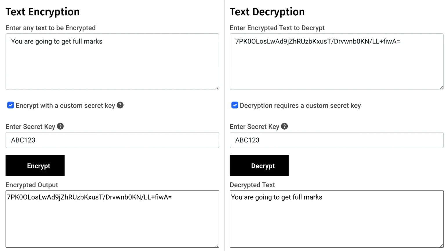
2.3.1 Symmetric Encryption
- •Uses the same key for encryption and decryption
- •Faster but less secure
2.3.2 Asymmetric Encryption
- •Uses public and private keys
- •Public key encrypts the message, and only the private key can decrypt it
- •Used in secure web communications (HTTPS)
2.3.3 Use of Public and Private Keys
- •Public keys are shared openly
- •Private keys remain confidential
- •Used in digital signatures and secure transactions
2.3.4 SSL (Secure Sockets Layer)
SSL (Secure Sockets Layer) and its successor TLS (Transport Layer Security) are cryptographic protocols that provide secure communication over the internet. SSL/TLS is used in HTTPS to encrypt data transmitted between a web browser and a web server.
Practice Question
Past Paper 2021(ii) Explain how the SSL connection is created.
Answer:
- •Uses (digital) certificates
- •Requested from web server by browser/client // browser/client asks web server to identify itself
- •Server sends SSL/digital signature to browser/client
- •Client and server agree on encryption method to use
- •That contains the server's public key
- •Browser checks authenticity of certificate
- •Then session key is generated
- •The transaction will begin // sends signal to server to start transmission
Practice Question
Past PaperIdentify an alternative protocol that could be used for secure transmission of data using the internet. [1]
Answer:
- •TLS (Transport Layer Security)
Practice Question
Past Paper3 Transport Layer Security (TS) protocol is used to secure the transmission of data over the Internet.
(a) Identify the two layers in the TLS protocol.
Layer 1
Layer 2 [2]
Answer:
- •Handshake layer
- •Record layer
Chapter Summary
This chapter covered data transmission methods, including packet switching, transmission modes, error detection techniques (parity checks, checksums, echo checks, check digits, ARQ), and encryption methods (symmetric and asymmetric). Understanding these concepts is essential for IGCSE O Level Computer Science.