10. Boolean Logic
SECTION 2: ALGORITHMS, PROGRAMMING AND LOGIC
Important Note
These notes cover the main points for revision. They are great for reviewing key concepts, but for in-depth understanding, always keep your textbook nearby for reference.
Boolean logic is the foundation of digital electronics and computer systems. This chapter covers logic gates, truth tables, logic circuits, and Boolean expressions used to design and analyze digital systems.
💡 Useful Resources: Practice logic circuits at logic.ly/demo and create diagrams at draw.io
Table of Contents
10.1 Logic Gate Symbols & Truth Tables
Logic gates are electronic circuits that process binary inputs (0/1) to produce a binary output.
- • Six logic gates in syllabus: NOT, AND, OR, NAND, NOR, XOR
- • Truth table: lists all possible input combinations and the resulting output
- • For n inputs → possible rows = 2n (e.g., 3 inputs → 8 rows)
Binary Values: 1 → True, 0 → False
10.1.1 NOT Gate
The NOT gate inverts the input. Output is 1 if input is 0, and output is 0 if input is 1.
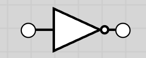
Truth Table
| A | NOT A |
|---|---|
| 0 | 1 |
| 1 | 0 |
10.1.2 AND Gate
The AND gate output is 1 only if both inputs are 1.
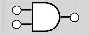
Truth Table
| A | B | A AND B |
|---|---|---|
| 0 | 0 | 0 |
| 0 | 1 | 0 |
| 1 | 0 | 0 |
| 1 | 1 | 1 |
10.1.3 OR Gate
The OR gate output is 1 if at least one input is 1.
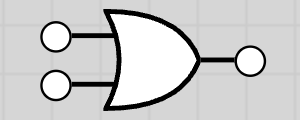
Truth Table
| A | B | A OR B |
|---|---|---|
| 0 | 0 | 0 |
| 0 | 1 | 1 |
| 1 | 0 | 1 |
| 1 | 1 | 1 |
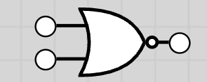
10.1.4 NAND Gate (NOT AND)
The NAND gate output is 1 except when both inputs are 1. It is the inverse of AND.
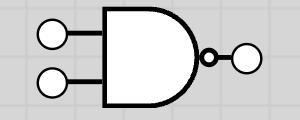
Truth Table
| A | B | A NAND B |
|---|---|---|
| 0 | 0 | 1 |
| 0 | 1 | 1 |
| 1 | 0 | 1 |
| 1 | 1 | 0 |
10.1.5 NOR Gate (NOT OR)
The NOR gate output is 1 only if both inputs are 0. It is the inverse of OR.
Truth Table
| A | B | A NOR B |
|---|---|---|
| 0 | 0 | 1 |
| 0 | 1 | 0 |
| 1 | 0 | 0 |
| 1 | 1 | 0 |
10.1.6 XOR Gate (Exclusive OR)
The XOR gate output is 1 if inputs are different. Output is 0 if inputs are the same.
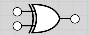
Truth Table
| A | B | A XOR B |
|---|---|---|
| 0 | 0 | 0 |
| 0 | 1 | 1 |
| 1 | 0 | 1 |
| 1 | 1 | 0 |
10.2 Logic Circuits, Expressions & Truth Tables
A logic circuit is a combination of gates to perform a task. There are three ways to represent logic:
1. Logic Circuit Diagram
Visual representation using gate symbols
2. Truth Table
Lists all inputs and corresponding output
3. Boolean Expression
Mathematical representation using operators
Conversion is possible between circuit ↔ truth table ↔ expression. Used in real systems: alarms, safety devices, sensors.
10.2.1 Boolean Algebra
Boolean algebra is the mathematical representation of logic using operators:
Operator Symbols
- • · or AND = AND operation
- • + or OR = OR operation
- • ̅ or NOT = NOT operation (inversion)
10.2.2 Operator Precedence
When evaluating Boolean expressions, operators are processed in the following order:
Precedence Order (Highest to Lowest):
- 1. Brackets ( )
- 2. NOT
- 3. AND
- 4. OR
Example: For the expression A AND B OR NOT C, the evaluation order is: NOT C first, then A AND B, then OR.
Key Terms
Logic Gate
Electronic device performing a logical operation (NOT, AND, OR, NAND, NOR, XOR)
Logic Circuit
Group of logic gates working together for a function
Truth Table
Lists all inputs and corresponding output
Boolean Algebra
Mathematical representation of logic (· = AND, + = OR, ̅ = NOT)
10.3 Worked Examples
Example 1: A AND B OR NOT C
Expression: A AND B OR NOT C
Evaluation order: NOT C first, then A AND B, then OR
Truth Table
| A | B | C | NOT C | A AND B | A AND B OR NOT C |
|---|---|---|---|---|---|
| 0 | 0 | 0 | 1 | 0 | 1 |
| 0 | 0 | 1 | 0 | 0 | 0 |
| 0 | 1 | 0 | 1 | 0 | 1 |
| 0 | 1 | 1 | 0 | 0 | 0 |
| 1 | 0 | 0 | 1 | 0 | 1 |
| 1 | 0 | 1 | 0 | 0 | 0 |
| 1 | 1 | 0 | 1 | 1 | 1 |
| 1 | 1 | 1 | 0 | 1 | 1 |
Example 2: X = (A AND NOT B) OR (NOT A AND B)
This expression is equivalent to XOR operation.
Truth Table
| A | B | NOT B | A AND NOT B | NOT A | NOT A AND B | X |
|---|---|---|---|---|---|---|
| 0 | 0 | 1 | 0 | 1 | 0 | 0 |
| 0 | 1 | 0 | 0 | 1 | 1 | 1 |
| 1 | 0 | 1 | 1 | 0 | 0 | 1 |
| 1 | 1 | 0 | 0 | 0 | 0 | 0 |
Example 3: Y = (A OR B) AND (NOT (A AND B))
Truth Table
| A | B | A AND B | NOT (A AND B) | A OR B | Y |
|---|---|---|---|---|---|
| 0 | 0 | 0 | 1 | 0 | 0 |
| 0 | 1 | 0 | 1 | 1 | 1 |
| 1 | 0 | 0 | 1 | 1 | 1 |
| 1 | 1 | 1 | 0 | 1 | 0 |
Example 4: Complex Logic Circuit
For complex circuits with intermediate outputs, work step by step through each gate.
Tip: When analyzing complex circuits, identify intermediate outputs (like P, Q) and build the truth table column by column, working from inputs to final output.